Pure Sine Wave Inverter Circuit Diagram Pcb
Harmonic and neutral to ground voltage reduction using isolation transformer; (available only in pdf file (274kb), click the link to download it)
EGS002 SINE WAVE INVERTER CIRCUIT Many circuits

But it is expensive to generate sine wave in an inverter.

Pure sine wave inverter circuit diagram pcb. Sine wave inverter circuit diagram with complete step by step program and coding, in this article i will discuss how to use push pull converter, sinusoidal pulse width modulation, h bridge and low pass lc filter to make pure sine wave inverter circuit diagram. Now let us look into the 3 phase inverter circuit and its ideal simplified form. It passes the high dc voltage for specified amounts of time so that the average power and rms voltage are the same as if it were a sine wave.
In such cases ups is used to provide pure sine wave to load. Similarly there are many devices which need pure sine wave to operate properly. As you can see this six mechanical switch setup is.
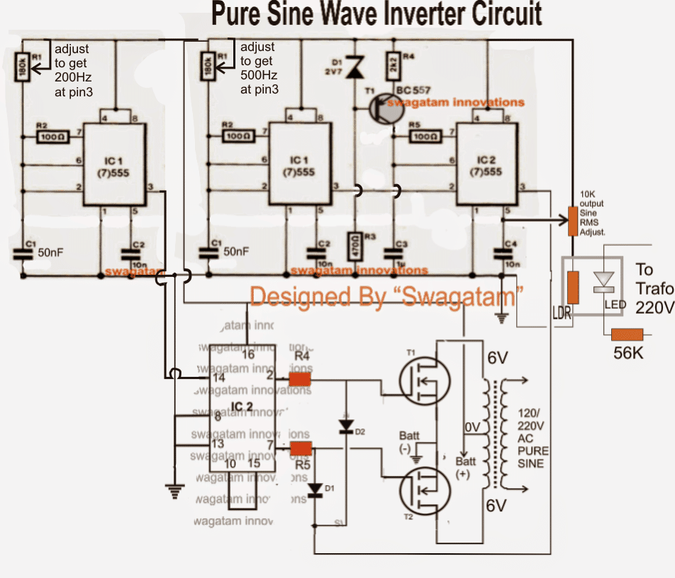
Las primeras impresiones suelen ser acertadas, y, a primera vista, los presuntos 38 segundos filtrados en reddit del presunto nuevo trailer de vengadores 4, con el oportuno presunto título de. Pure sine wave inverter with led and lcd the inverter pcb is easy to assemble by following the label of the components to be inserted. In the above section we learned the basic version of ic sg3525 designed to produce a modified sine wave output when used in an inverter topology, and this basic design cannot be enhanced to produce a pure sinewave waveform in its typical format.
The diy inverter board can handle up to 1kw (depending the transfor… Of course, you need a 1500w or 2000w (better) true sine wave inverter at 24v input voltage. The inverter must be a pure sine inverter.
Thanks in advance buy a programmer. The circuit diagram of mosfet inverter. Car batteries for powering you home?
The circuit is very simple; Registration to this forum is free! No modified sine waves are acceptable.
Its quality is excellent and almost all electrical and electronic appliances work well in sine wave inverter. We do insist that you abide by the rules and policies detailed below. You just have to program the arduino board.
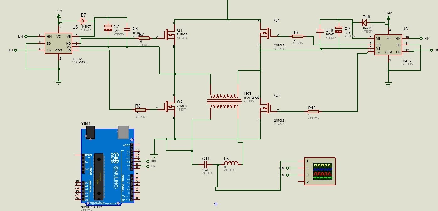
The project is based on the low cost egs002 spwm driver board module. In the last article we learned how to generate sine wave pulse width modulation or spwm though arduino, we are going to use the same arduino board to make the proposed simple pure sine wave inverter circuit.the design is actually extremely straightforward, as shown in the following figure. Diy cheap 1000w pure sine wave inverter (12v to 110v/220v):
But in power system use of power converters inject harmonics and voltage wave form distortion in main power supply. Pure sine wave inverter using arduino; Modified sine wave, and pure sine wave1.
Circuit which i could use with this circuit and if possible suggest me how to convert this square wave inverter to a sine wave inverter. Although the modified squarewave or sinewave output could be ok with its rms property and. I recommend a 24v inverter because the currents at 12v will exceed 1500w/12v/0.9 ~ 140 a and the conductors will be very thick, heavy and hard to work with them :
Engmanish dear all members, i am very newer to this microchip programming how & what to do as i want to make use of this controller for making pure sine wave 1kv 1phase 230vac ups control. Academia.edu is a platform for academics to share research papers. The pin #9, #10 and #11 are the pwm pins have the capability to produce analog voltage level as described before.
Gps based high efficient dual axis solar. A modified sine wave can be seen as more of a square wave than a sine wave; October 29, 2014, 7:24 am.
Sir do you have a diagram of a pure sine wave inverter? Most of the beginner to intermediate skilled hobbyists may know how to make a square wave inverter, but only few of them try patiently and make a pure sine wave inverter, that’s because the complexity involved in the construction of the circuit. To avoid change in frequency to reach to the input of induction machine ups is used.
I want 250 watt 220v 50 hz pure sine wave circuit diagram. Var compensation using thyristor switched capacitor; Tipped pcbn inserts in 80 degree diamond shape c for hard turning ferrous metals of cast iron and hardened steel, the cbn insert cutting edges are made with polycrystalline cubic boron nitride, indexable inserts with cbn tips are precision cutting tools, which are used in cnc fine finish machining and turning roller, bearing, pumps, automobile brake disk, aircraft jet engine.
Mathematical manipulation of pure sine wave inverter using atmel 89s2051 didik rostyono and harsono hadi explain how to produce the sinewave output inverter using the atmel microcontroller! Square wave to sine wave converter circuit is an important analog circuit that converts square waveforms to sine waveforms.it has a broad spectrum of applications in many different areas of electronics, such as in mathematical operations, acoustics, audio application, inverters, power source, function generator, etc. Power from the grid is carefully regulated to get a pure sine wave and also the sine wave radiate the least amount of radio power during long distance transmission.
The inverter executed in this circuit can be a square wave, & it works with devices like which do not need pure ac sine wave. Modified sine wave inverter circuit. Sine wave inverter circuit description.
Design real time battery monitoring system;
Make This 1KVA (1000 watts) Pure Sine Wave Inverter Circuit Circuit Diagram Centre

Pure Sine Wave Inverter Circuit Using IC 4047
SG3525 Pure Sinewave Inverter Circuit

300 Watts PWM Controlled, Pure Sine Wave Inverter Circuit with Output Voltage Correction

Pin by Lloyd Flemmings on Power supply circuit in 2020 Sine wave, Electronic circuit projects

sg3524 pure sine wave inverter circuit diagram pcb SHEMS

single phase pure sine wave inverter using arduino
Pure Sine Wave Inverter Pcb Schematic and Components Name EEenginners

Pure Sine Wave Inverter Circuit Diagram Pdf Circuit Diagram Images

true sine wave inverter circuit diagram ireleast,Circuit diagram,True Sine Wave Inverter

Pure Sine Wave Inverter Circuit Diagram Free Download Home Wiring Diagram

Circuits Inverter Pure Sine Wave Circuit Diagram Images

Modified Sine Wave Inverter Circuit Using IC 3525, with Regulated Output and Low Battery Protection

1KVA (1000 watts) Pure Sine Wave Inverter Circuit using 555 ic Expert Circuits

sg3524 pure sine wave inverter circuit diagram pcb SHEMS

diagrammide pure sine wave inverter circuit diagram download

300 Watts PWM Controlled Pure Sine Wave Inverter Circuit Homemade Circuit Projects
Multilevel 5 Step Cascaded Sine Wave Inverter Circuit

Making a 3KVA Modified Sine Wave Inverter Circuit
